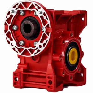
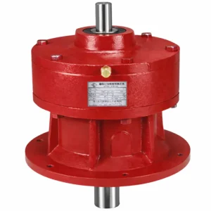
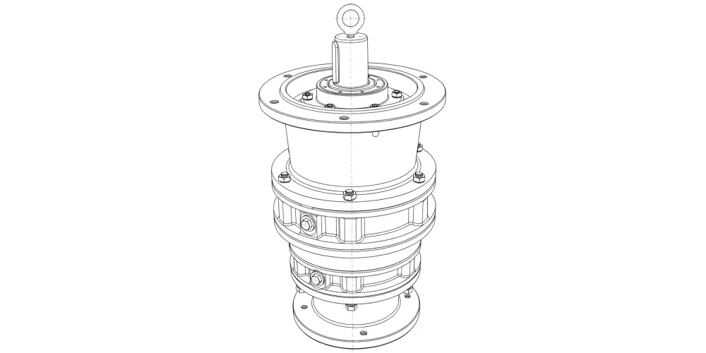
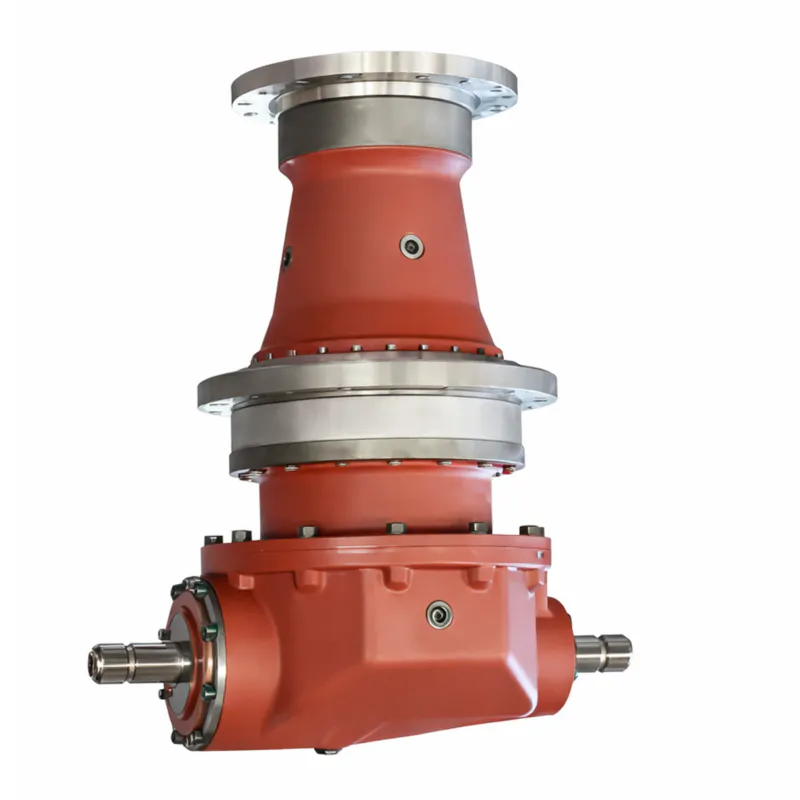
Riduttore cicloidale serie EP-BLE XLE a doppio stadio con flangia verticale
The EP-BLE XLE Series Cycloidal Gearbox in Double Stage Vertical Flange-mounted configuration is a precision-engineered cycloidal gear reducer built around the classical planetary cycloidal pin-gear transmission principle. Unlike conventional helical or worm-gear units, the cycloidal drive replaces straight tooth contact with a rolling-mesh interaction between a precisely profiled cycloidal disc and a ring of hardened cylindrical pins — a geometry that distributes load across many teeth simultaneously, yielding exceptionally high torque density in a compact housing.
The double-stage architecture multiplies the reduction capability of a single cycloidal stage, unlocking gear ratios that reach into the thousands without sacrificing the smooth, near-vibration-free output characteristic of this drive family.
This industrial cycloidal gearbox is widely deployed across petroleum refining, environmental processing, chemical blending, cement production, metallurgy, power generation, textile processing, pharmaceutical manufacturing, food-grade conveying, and printing — anywhere precise speed reduction and high overload capacity must coexist in a small installation envelope. The EP-BLE XLE series meets these demands with a combination of robust cast-iron housings, case-hardened alloy steel internals, and a lubrication system designed for long-interval, low-maintenance operation.
High-torque, low-backlash cycloidal speed reducer engineered for demanding industrial vertical-drive applications.
Stage 1: 9–87 | Stage 2: 121–5133
Up to 94%
Vertical Flange (XLD / BLY)
Cycloidal Pin-Gear Planetary
1. Technical Specifications Of Cycloidal Gearbox
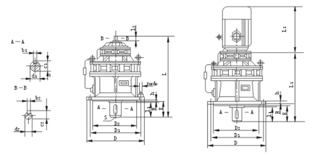
XLE Series Cycloidal Gearbox
| Modello | Mounting dimension | Produzione | Ingresso | D | Dual | Gear motor | Weight kg | ||||||||||||||
|---|---|---|---|---|---|---|---|---|---|---|---|---|---|---|---|---|---|---|---|---|---|
| D₁ | D₂ hS | E | H | R | S | n | do | d₁ h6 | b₁ | c₁ | l₁ | d₂ h6 | b₂ | c₂ | l₂ | L | L₁ | L₂ | |||
| 31 | 200 | 170 | 50 | 15 | 4 | M8 | 6 | 12 | 35 | 10 | 38 | 45 | 15 | 5 | 17 | 25 | 230 | 310 | 258 | 35 | |
| 42 | 230 | 200 | 79 | M10 | 45 | 14 | 48.5 | 63 | 260 | 384 | 326 | 75 | |||||||||
| 53 | 310 | 270 | 93 | 20 | 5 | M12 | 8 | 16 | 55 | 16 | 59 | 79 | 18 | 6 | 20.5 | 35 | 340 | 457 | 383 | See 7 | 94 |
| 63 | 360 | 316 | 92 | 22 | 18 | 65 | 18 | 69 | 80 | 400 | 519 | 447 | 149 | ||||||||
| 74 | 390 | 345 | 114 | 80 | 22 | 85 | 98 | 22 | 24.5 | 40 | 430 | 589 | 508 | 193 | |||||||
| 84 | 450 | 400 | 112 | 30 | 6 | M16 | 12 | 22 | 90 | 25 | 95 | 110 | 22 | 6 | 24.5 | 40 | 490 | 633 | 552 | 280 | |
| 85 | 656 | 566 | 310 | ||||||||||||||||||
| 95 | 520 | 455 | 117 | 35 | 8 | M20 | 100 | 28 | 106 | 129 | 30 | 8 | 33 | 45 | 580 | 745 | 655 | 495 | |||
| 106 | 590 | 520 | 174 | 40 | 10 | 110 | 116 | 140 | 35 | 10 | 38 | 54 | 650 | 855 | 754 | 667 | |||||
| 117 | 800 | 680 | 210 | 45 | 2-M20 | 12 | 38 | 130 | 32 | 137 | 184 | 40 | 12 | 43 | 65 | 880 | 1081 | 963 | 1290 | ||
BLE Series Cycloidal Gearbox
| Modello | Mounting dimension | Produzione | Ingresso | D | Dual | Gear motor | Weight kg | ||||||||||||||
|---|---|---|---|---|---|---|---|---|---|---|---|---|---|---|---|---|---|---|---|---|---|
| D₁ | D₂ hS | E | H | R | S | n | do | d₁ h6 | b₁ | c₁ | l₁ | d₂ h6 | b₂ | c₂ | l₂ | L | L₁ | L₂ | |||
| 31 | 200 | 170 | 50 | 15 | 4 | M8 | 6 | 12 | 35 | 10 | 38 | 45 | 15 | 5 | 17 | 25 | 230 | 310 | 258 | 35 | |
| 42 | 230 | 200 | 79 | M10 | 45 | 14 | 48.5 | 63 | 260 | 384 | 326 | 75 | |||||||||
| 53 | 310 | 270 | 93 | 20 | 5 | M12 | 8 | 16 | 55 | 16 | 59 | 79 | 18 | 6 | 20.5 | 35 | 340 | 457 | 383 | See 7 | 94 |
| 63 | 360 | 316 | 92 | 22 | 18 | 65 | 18 | 69 | 80 | 400 | 519 | 447 | 149 | ||||||||
| 74 | 390 | 345 | 114 | 80 | 22 | 85 | 98 | 22 | 24.5 | 40 | 430 | 589 | 508 | 193 | |||||||
| 84 | 450 | 400 | 112 | 30 | 6 | M16 | 12 | 22 | 90 | 25 | 95 | 110 | 22 | 6 | 24.5 | 40 | 490 | 633 | 552 | 280 | |
| 85 | 656 | 566 | 310 | ||||||||||||||||||
| 95 | 520 | 455 | 117 | 35 | 8 | M20 | 100 | 28 | 106 | 129 | 30 | 8 | 33 | 45 | 580 | 745 | 655 | 495 | |||
| 106 | 590 | 520 | 174 | 40 | 10 | 110 | 116 | 140 | 35 | 10 | 38 | 54 | 650 | 855 | 754 | 667 | |||||
| 117 | 800 | 680 | 210 | 45 | 2-M20 | 12 | 38 | 130 | 32 | 137 | 184 | 40 | 12 | 43 | 65 | 880 | 1081 | 963 | 1290 | ||
2. Five Quick Facts You Need to Know
- Double-stage planetary cycloidal design delivers reduction ratios from 121 to 5,133, far beyond typical single-stage units.
- Vertical flange-mounted configuration (XLD / BLY) saves floor space and integrates directly with motor flanges — no coupling adapter needed.
- Rolling contact on all meshing surfaces eliminates sliding friction, sustaining first-stage efficiency of up to 94% even under heavy load.
- Simultaneous multi-tooth engagement (high contact ratio) dramatically reduces vibration and operating noise across all speed ranges.
- Input and output shafts share a common central axis, keeping the overall footprint over one-third smaller than equivalent worm or spur-gear units.
3. How the Cycloidal Gearbox Works?
At the heart of every cycloidal drive gearbox is a 180°-offset double eccentric sleeve mounted on the input shaft. Two rocker-arm roller bearings are seated on the eccentric sleeve, forming an H-shaped sub-assembly. A pair of cycloidal discs is eccentrically mounted on these bearings so that, as the input shaft rotates, each disc traces a hypocycloidal path inside the pin-gear ring. The tooth profile of the cycloidal disc is calculated so that it is always in full-face rolling contact with the pin gear rather than sliding contact — this is the fundamental reason cycloidal reducers outlast worm drives in continuous-duty applications.
Speed reduction in the first stage comes from the tooth-count difference between the cycloidal disc and the pin ring — typically one fewer tooth on the disc than pins in the ring. The resulting output is carried through a set of output pins that pass through holes in the cycloidal disc, converting the eccentric orbital motion into pure rotation. In the EP-BLE XLE double-stage variant, a second equivalent assembly is driven by the first-stage output shaft, compounding the ratio to values between 121:1 and 5,133:1 while preserving the smooth, shock-absorbing output quality of the single-stage unit.
Because all meshing surfaces roll rather than slide, friction losses are minimal and the unit sustains first-stage efficiency around 94%. The double-stage overall efficiency is somewhat lower due to two power-transmission stages, yet remains substantially better than a comparable two-stage worm gearbox under the same load conditions. The balancing of the two cycloidal discs against each other almost completely eliminates the dynamic imbalance forces that create vibration and noise in single-disc designs.
4. Five Key Product Advantages Of Cycloidal Gearbox
① Ultra-High Reduction in One Package
The double-stage configuration delivers ratios up to 5,133:1, eliminating the need for external gearbox cascades or belt-reduction stages. This simplifies machine design, reduces coupling alignment risk, and shrinks the drivetrain footprint considerably — a decisive advantage in retrofit and space-critical installations.
② Superior Torque Density vs. Worm Gearbox
Where a worm gearbox of equivalent output torque might weigh three times as much, the compact cycloidal gearbox design keeps weight and volume to a minimum. Rolling-contact tooth engagement means power losses stay low even at high reduction ratios — an area where worm drives are well-known to underperform, especially at ratios above 40:1.
③ Minimal Backlash for Precise Positioning
With backlash held to ≤ 1 arc-minute, this precision cycloidal gearbox is fully suited for indexing tables, robotic joints, and servo-driven positioning systems. The inherently tight mesh geometry achieves this without requiring the preload adjustments that add complexity and wear risk to planetary gear drives.
④ Robust Overload & Shock Tolerance
The high contact ratio — with many pin-and-disc tooth pairs sharing the load at any instant — creates an inherent shock-absorption effect not achievable in single-tooth-contact spur or helical gears. The EP-BLE XLE series tolerates short-term peaks up to 2× rated torque, making it reliable in cyclic-load applications such as crushers, agitators, and reciprocating conveyors.
⑤ Simplified Maintenance & Long Service Life
The component count is deliberately kept low — fewer parts means fewer wear interfaces. The splash-lubrication system (ISO VG 220 gear oil) needs attention only every 5,000 operating hours under normal conditions. Bearing inspection uses a standard feeler-gauge clearance check, and the unit can be fully disassembled and reassembled with common workshop tooling, reducing downtime across the service lifetime.
5. Material & Construction
The long operational life of an industrial cycloidal gearbox depends directly on the materials chosen for each sub-assembly. Every component in the EP-BLE XLE series is specified to perform under continuous industrial-grade loading.
| Componente | Material / Standard | Heat Treatment / Hardness |
|---|---|---|
| Cycloidal Discs | Alloy steel — 20CrMnTi / AISI 4118 equivalent | Case-hardened; HRC 58–62 |
| Pin Gear Pins | Bearing-grade alloy steel — GCr15 / AISI 52100 | Through-hardened; HRC 60–64 |
| Input / Output Shafts | 42CrMo alloy steel (AISI 4140 equivalent) | Induction-hardened journal; Ra ≤ 0.8 μm |
| Eccentric Sleeve | 42CrMo alloy steel | Quenched & tempered; HB 280–320 |
| Gearbox Housing | Grey cast iron — HT250 | Stress-relieved; machined mating faces |
| Output Flange | Ductile iron — QT450 | Normalised; bolt-hole tolerance H7 |
| Roller Bearings | ISO-rated deep-groove & cylindrical roller bearings | L10 life ≥ 20,000 hr at rated load |
| Seals | NBR lip seals (standard); FKM available for chemical duty | — |
Surface roughness on all shaft mating diameters is held to Ra ≤ 0.8 μm. Shaft diameter ovality and taper are maintained within 0.015–0.025 mm of true round — deviations up to 0.02 mm are acceptable for continued service; anything beyond 0.02 mm triggers a refurbishment cycle to prevent accelerated bearing wear.
6. Scenari applicativi
The EP-BLE XLE cycloidal gearbox double stage vertical flange-mounted configuration is purpose-designed for applications demanding a vertical output axis, high torque, and reliable continuous-duty operation. The following scenarios represent the most common deployment environments.
Chemical & Petroleum Processing
Agitator and reactor drives in refineries and chemical plants run continuously under corrosive atmospheres. The sealed housing, optional FKM shaft seals, and IP65 protection keep the riduttore di velocità cicloidale operational where oil or chemical vapour would degrade less-protected units.
Environmental & Wastewater Treatment
Slow-speed sludge scrapers and aeration-basin rakes require torque-dense drives at very low RPM — ratios exceeding 1,000:1. The double-stage cycloidal reducer delivers these ratios reliably over years of immersed or humid-environment service without the efficiency penalty associated with multi-stage worm arrangements.
Cemento e materiali da costruzione
Kiln drives, clinker cooler fans, and vertical-shaft mixers in cement plants demand heavy overload tolerance and minimal gearbox vibration to protect adjacent machinery. The high contact-ratio cycloidal mesh naturally absorbs shock impulses and extends intervals between planned maintenance shutdowns.
Food, Pharmaceutical & Packaging
Hygienic environments require drives that can be cleaned down without lubricant contamination risk. The EP-BLE XLE series can be specified with food-grade grease and stainless-steel external hardware, meeting FDA 21 CFR and EU 1935/2004 contact-material requirements for indirect food contact applications.
Macchinari tessili e da stampa
Precise, low-noise operation is critical in textile dyeing lines and high-speed printing presses. The low backlash and smooth torque delivery of the precision cycloidal gearbox prevent registration errors, fabric slippage, and registration shift — issues that directly affect finished-product quality.
Attività minerarie, metallurgiche e industria pesante
Ore conveyor drives, bucket-wheel reclaimers, and casting-table positioners subject gearboxes to severe shock and vibration. The simultaneous multi-tooth engagement of the cycloidal drive gearbox distributes impact loads across many contact surfaces, reducing peak stress concentrations and extending service intervals well beyond those achievable with spur-gear or worm alternatives.
7. Regulatory Compliance & Industry Standards
Mechanical power-transmission equipment is subject to a range of safety, environmental, and quality regulations across export markets. The EP-BLE XLE cycloidal gearbox is designed and manufactured to align with the following frameworks:
| Regione / Standard | Requisito | Relevance |
|---|---|---|
| European Union — CE Marking | EU Machinery Directive 2006/42/EC | Mandatory for gearbox units supplied as machine components into the EU market. |
| EU — RoHS II (2011/65/EU) | Restriction of Hazardous Substances | Applies to electrical/electronic components integrated with the drive motor assembly. |
| USA — OSHA 29 CFR 1910.217 | Machine guarding for power-transmission equipment | Requires proper guarding of exposed rotating shafts and couplings on US-market installations. |
| USA — UL / NEMA Standards | Motor flange interface compliance (NEMA C-face) | Flange-mounted units can be configured to accept NEMA C-face or IEC B5/B14 motor flanges. |
| Quality — ISO 9001:2015 | Quality Management System | Manufacturing quality system covering design, production, inspection, and after-sale support. |
| ISO 14001:2015 | Environmental Management System | Governs waste disposal, lubricant handling, and environmental impact during manufacture. |
| Gear Accuracy — ISO 1328 / DIN 3961 | Gear-tooth accuracy classes | Cycloidal discs and output pins are manufactured to DIN 6 / ISO 7 accuracy grades. |
| Australia / New Zealand — AS/NZS 4024 | Safety of machinery — Guards for power transmission | Applicable to OEM integrators supplying ANZ markets; shaft guards and coupling covers required. |
| Food Industry — FDA 21 CFR / EU 1935/2004 | Food-contact material requirements | Optional food-grade configuration available with H1-rated lubricant and stainless hardware. |
It remains the responsibility of the OEM integrator or end-user to confirm that the complete machine installation meets all locally applicable regulations. Our engineering team can supply documentation packages — including material certificates (EN 10204 3.1), gear-accuracy measurement reports, and third-party test certificates from SGS, TÜV, or BV — on request.
8. Maintenance & Daily Inspection Guide
A systematic inspection routine protects against unplanned downtime. The three critical areas to monitor on any riduttore cicloidale are bearings, the cycloidal disc-and-pin contact surfaces, and the output shaft.
Bearing Inspection
Clean the target bearing with heated mineral oil until the inner race turns freely by hand in all radial directions without binding. Once clean, use a feeler gauge to measure running clearance. Any binding, roughness on rotation, or clearance outside the manufacturer's table is cause for replacement before the unit re-enters service. Preemptive bearing changes are far less expensive than emergency repairs following a catastrophic seizure.
Cycloidal Disc & Pin Inspection
The disc profiles must be free of chipping, cracking, or spalling — any of these defects on a tooth surface constitutes a mandatory stop-and-replace condition. Unlike spur gears where a single chipped tooth might continue to function for some time, a damaged cycloidal disc rapidly propagates wear to adjacent pin contacts and can cause debris contamination of the entire lubricant charge.
Shaft Inspection
Measure shaft diameter ovality and taper at multiple cross-sections. Values within 0.015–0.025 mm of nominal are acceptable for continued operation. A deviation of up to 0.02 mm is within re-use tolerance; anything beyond 0.02 mm requires a refurbishment cycle (re-grinding or shaft replacement). Shaft key-slot widths should be within 0.04 mm of the limit size; shafts exceeding this tolerance must be replaced immediately to prevent key-and-slot fretting that accelerates wear progression.
9. Chi siamo
We are a dedicated manufacturer of precision cycloidal gearboxes, operating a purpose-built production facility equipped with CNC gear-grinding centres, coordinate-measuring machines (CMM), spectral analysers, and dedicated hardness-testing stations. Our engineering team — composed of mechanical engineers with specialisations in gear geometry, tribology, and fatigue design — oversees every stage from initial drawing review through final dimensional and performance validation.
The cycloidal gearbox supplier capabilities in our facility cover the complete BLE and XLE cycloidal gearbox series in standard and custom configurations, including non-standard reduction ratios, special shaft diameters, extended temperature ratings, and food-grade or explosive-atmosphere (ATEX) compliant variants.
Workshop


10. Related Products & Compatible Components
A complete drivetrain solution goes beyond the gearbox itself. We supply a full range of compatible power-transmission components engineered to work seamlessly with our cycloidal gearbox series — giving you the convenience of a single-source supplier for the entire drive system.
Riduttore epicicloidale
Realizzati con ingegneria di precisione e una costruzione robusta, i nostri riduttori offrono una moltiplicazione della coppia affidabile, un gioco minimo e una maggiore capacità di carico.
Motori di azionamento
Disponiamo a magazzino di motori a induzione standard IEC e NEMA con flangia C, pre-accoppiati alle dimensioni della flangia delle serie di riduttori BLE e XLE. Sono disponibili motori trifase e monofase con efficienza IE3, nonché varianti per inverter, progettate per funzionare a coppia piena a basse velocità quando controllate tramite VFD, un requisito comune nelle applicazioni con agitatori e nastri trasportatori.
Domande frequenti
Q1. What is the difference between a cycloidal gearbox and a planetary gearbox for vertical flange-mounted industrial applications in the USA?
Cycloidal gearboxes use rolling pin-gear contact across many simultaneous tooth engagements, whereas standard planetary gearboxes rely on a smaller number of helical or spur planet-gear contacts. In vertical flange-mounted configurations, the cycloidal design typically delivers higher shock-load tolerance, lower backlash without requiring preload adjustment, and competitive efficiency at very high reduction ratios — areas where planetary gearboxes can struggle once ratios exceed approximately 100:1 in a single stage.
Q2. What is the expected bearing L10 life and how does it affect the total cost of ownership for a high-torque cycloidal reducer used in a mining conveyor system in the American Southwest?
Bearings in the EP-BLE XLE series are selected for an L10 life of ≥ 20,000 operating hours at rated load — equivalent to roughly 8.3 years of 24/7 service at full rated torque, or considerably longer if the unit operates at partial load for a significant portion of its duty cycle. In a mining application running two 10-hour shifts per day, that corresponds to approximately 11–14 years before a statistical 10% probability of bearing replacement is reached. This long bearing interval, combined with 5,000-hour oil changes, keeps total maintenance costs substantially below those of higher-maintenance worm-drive alternatives over the gearbox service lifetime.
Q3. Which industries in the United States most commonly use a compact cycloidal gearbox for vertical-axis drive systems?
The primary US industrial sectors are wastewater treatment (agitators, scrapers), food and beverage processing (vertical mixer drives), pharmaceutical manufacturing (granulator and blender drives), chemical processing (reactor agitators), and cement/aggregates (vertical-shaft mill drives). The combination of high torque density, low maintenance, and small envelope makes the cycloidal drive the preferred solution wherever floor space is limited and continuous duty reliability is non-negotiable.
Q4. What lubrication oil type and change interval does the EP-BLE XLE cycloidal speed reducer require for continuous 24/7 operation?
Standard units are filled with ISO VG 220 mineral gear oil using the oil-bath (splash) method. For 24/7 continuous-duty service at ambient temperatures up to +40 °C, the recommended change interval is 5,000 operating hours or 12 months, whichever comes first. For high-ambient or extreme-cycling duties, synthetic ISO VG 220 can extend this interval; food-grade H1-classified lubricants are available for hygienic applications.
Q5. Can a cycloidal gearbox automation system handle variable-frequency drive (VFD) operation at low speeds without losing torque or overheating?
Yes. The cycloidal gearbox itself is mechanically passive and does not generate heat — it is the input motor that requires consideration in VFD applications. Pairing the gearbox with an inverter-duty motor rated for operation down to 10% of base speed at full torque is the standard approach. Because the double-stage cycloidal unit already provides a very high reduction ratio, the motor can run at higher, more thermally favourable speeds to achieve the target output shaft speed.
Q6. When should I choose a small cycloidal gearbox over a helical gear motor for a precise low-speed conveyor application in a pharmaceutical plant?
A compact cycloidal gearbox is preferable over a helical gear motor when you need a reduction ratio exceeding roughly 50:1 in a single drive unit, because multi-stage helical arrangements become mechanically complex and acoustically noisy at high ratios. The cycloidal option also provides significantly lower backlash, which matters in pharmaceutical conveying where precise metering or indexing is required. If the ratio is below 30:1 and noise is not a primary concern, a standard helical gear motor may be more cost-effective.
Q7. How does a cycloidal gearbox versus a worm gearbox perform at reduction ratios above 100:1 in a chemical plant agitator application?
Worm gearboxes at ratios above 50:1 typically see efficiency drop below 50–60% because the high helix-angle contact creates substantial sliding friction. At 100:1 single-stage, efficiency can fall below 40%. By contrast, the cycloidal drive sustains approximately 90% overall efficiency in a double-stage 100:1 configuration because all tooth contact remains rolling rather than sliding. For continuous agitator duty, this efficiency gap directly translates to lower electricity costs and substantially less heat build-up inside the unit.
Redattore: PXY