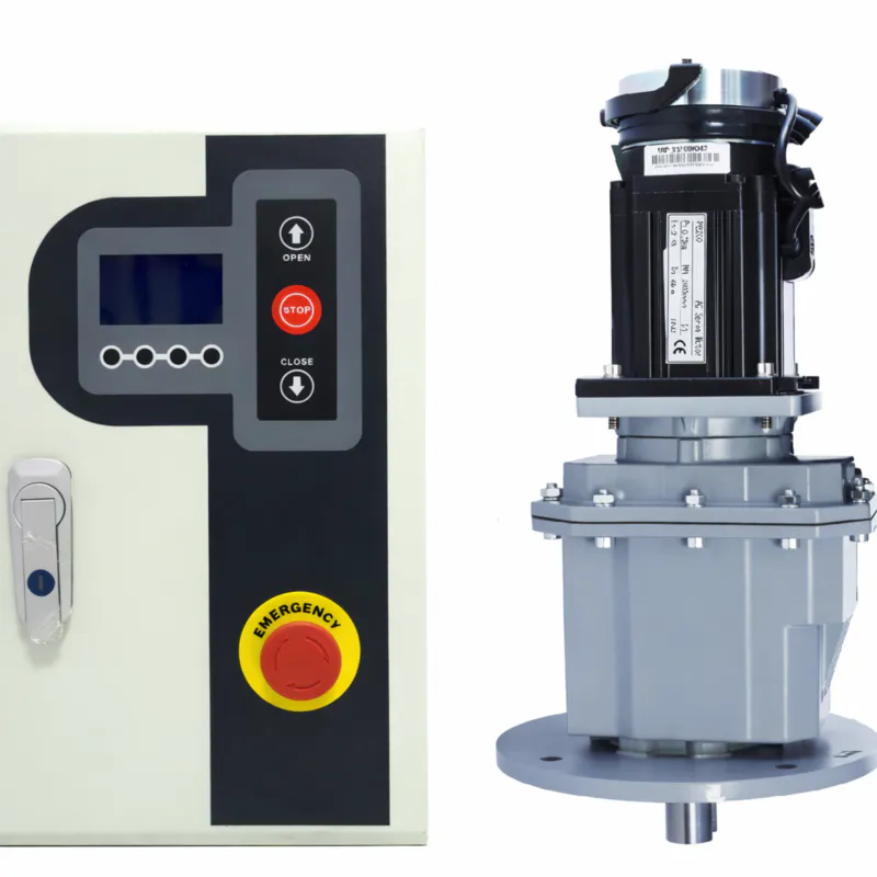
EP-Door Gearbox Reducer & Motor
The EP-series door gearbox reducer is a compact, high-torque gear unit engineered to drive heavy automatic doors in industrial and commercial settings — converting the high-speed rotation of a paired drive motor into the slow, forceful output needed to open, close, and hold door panels weighing up to 600 kg.
Four frame sizes cover a power range of 0.55 kW to 1.5 kW with gear ratio options from 5 : 1 to 100 : 1, giving specification engineers the flexibility to match door weight, target opening speed, and cycle-rate requirements precisely — rather than accepting a compromise in an off-the-shelf gear motor assembly.
1. Technical Specifications — EP-Series Door Gearbox Reducer
The table below covers all four gear reducer frame sizes. Values reflect standard production configurations; application-specific variants (non-standard ratios, special shaft geometries, low-temperature options) are available on request.
| Parameter | RV050 Worm | RV063 Worm | BRC01 Helical-Bevel | BRC02 Helical-Bevel |
|---|---|---|---|---|
| Rated Output Torque (Nm) | Up to 80 | Up to 150 | Up to 250 | Up to 380 |
| Peak / Breakaway Torque (Nm) | 120 | 225 | 375 | 570 |
| Gear Ratio Range | 5 – 50 | 5 – 80 | 10 – 80 | 10 – 100 |
| Input Speed — Max (RPM) | 3 000 | 3 000 | 3 000 | 3 000 |
| Gear Stage Type | Single-stage worm gear | Two-stage helical-bevel gear | ||
| Mechanical Efficiency | ≥ 72 % | ≥ 92 % | ||
| Self-Locking (back-drive) | Yes (at ratio ≥ 20 : 1) | No — brake required if needed | ||
| Matched Motor Power (kW) | 0.55 | 0.75 | 1.1 | 1.5 |
| Motor Type (standard) | Brushless DC (BLDC) with integrated controller | |||
| Supply Voltage | 24 V DC / 48 V DC / 110–240 V AC (controller-selectable) | |||
| Enclosure Rating | IP55 standard | IP65 on request | |||
| Ambient Temperature | –20 °C to +45 °C ( –4 °F to 113 °F) | |||
| Gear Housing Material | Die-cast aluminium alloy EN AC-46000; SS option available | |||
| Lubrication | ISO VG 220 synthetic; oil-bath; service interval 8 000 h | |||
| Output Bearing L10 Life | ≥ 20 000 h at rated load | |||
| Noise Level (no-load) | < 62 dB(A) at 1 m | |||
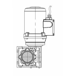
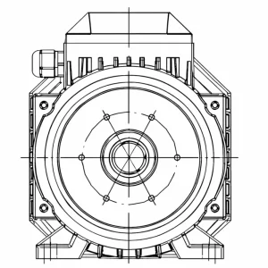
| Mounting Options | Flange-mount (B5/B14) · Foot-mount · Hollow-shaft adapter | |||
| Approx. Weight (gear unit only) | 4.2 kg | 6.8 kg | 9.5 kg | 13.2 kg |
| Gear Accuracy Class | ISO 14521 (worm) | DIN 6 / ISO 6336 (helical) | ||
* All specifications based on standard production data. Verify against certified engineering drawing before final design commitment.
2. Five Key Engineering Facts of door gearbox reducer
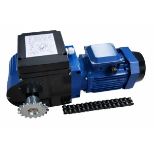
▶ Gear reducer models: RV050 (worm), RV063 (worm), BRC01 (helical-bevel), BRC02 (helical-bevel) — four gear unit configurations optimized for different door weight classes.
▶ Gear ratio range: 5: 1 to 100: 1 in standard steps, selectable at time of order to match the required output speed and torque at the door drum or rack.
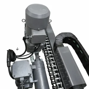
▶ Drive package: The gear reducer ships as a standalone unit or as a matched assembly with an integrated brushless DC drive motor and controller — both options use the same gear housing for field interchangeability.
▶ Efficiency: BRC helical-bevel gear stage ≥ 92 %; RV worm gear stage ≥ 72 % with self-locking characteristic — each suited to a different duty profile.
▶ Modular cartridge: The drive motor detaches from the gear head without disturbing shaft alignment, enabling independent replacement of either sub-assembly and cutting mean-time-to-repair significantly.
3. What Is a Door Gearbox Reducer — and What Role Does It Play?
A door gearbox reducer — also described in engineering documentation as a door gear reducer, door speed reducer, or simply a door gear unit — is the core mechanical sub-assembly in any powered door system. Its function is straightforward: accept high-speed, low-torque rotation from a drive motor at the input shaft, step down the speed through one or more gear stages, and deliver slow, high-torque rotation at the output shaft. That output connects to the door's torsion drum, chain sprocket, rack-and-pinion rail, or belt drive, translating rotational energy into linear door movement.
What makes specifying a door gearbox reducer different from selecting a general-purpose gear unit is the combination of duty characteristics unique to door applications. Most industrial gearboxes are designed for continuous, steady-state operation at a fixed load. A door drive, by contrast, operates in short bursts — a typical 10-second opening cycle, a dwell period, then a 10-second closing cycle — potentially hundreds of times per day. Each cycle involves a start under load, peak torque demand at breakaway, brief steady-state travel, and a controlled deceleration. The gear reducer must handle this repetitive transient loading throughout a service life measured in millions of cycles, not operating hours.
The EP-series door gearbox reducer was designed around these specific demands. The worm gear configurations (RV050, RV063) provide inherent back-driving resistance — a property that holds the door panel stationary under gravity or wind pressure without requiring a separate holding brake, which matters for fire-rated and security applications. The helical-bevel configurations (BRC01, BRC02) trade that self-locking characteristic for significantly higher mechanical efficiency, which matters when a door cycles two hundred or more times per day and energy cost adds up over a three-year operational horizon.
Understanding the distinction between the door gear reducer and the drive motor is also important for maintenance planning. The gear reducer is the long-life component in the assembly — properly lubricated and sealed, a quality gear unit will outlast two or three motor replacement cycles. Sourcing a door gearbox reducer that separates cleanly from the motor — as the EP modular cartridge design does — means that a motor failure does not require replacement of the entire gear unit, and a gear-stage wear event does not require purchasing a new motor. Each sub-assembly is serviced or replaced on its own schedule.
4. Five Reasons Engineers Specify the EP Door Gearbox Reducer
1. Gear Reducer First, Motor Second
The EP platform is designed as a door gear reducer — the gear unit is the primary structural and torque-handling component. The drive motor attaches to a standardized input flange, which means you can pair the same gear housing with different motor types: brushless DC, AC induction, or permanent-magnet synchronous. This separation of concerns protects your gear unit investment when drive-motor technology changes.
2. Two-Gear Stages — Matched to Duty
The worm stage in the RV-series door speed reducer delivers mechanical self-locking — the door stays put on power failure without an external brake. The helical-bevel stage in the BRC-series door gear reducer sacrifices the self-locking for 92 %+ efficiency. Having both architectures in the same frame family means you select by duty requirement, not by what the supplier happens to stock.
3. Gear Unit and Motor Replace Independently
The motor cartridge detaches from the gear housing in under fifteen minutes using standard hand tools. A bearing failure in the gear unit does not require motor replacement; a burned motor winding does not mean sourcing a new door gearbox reducer. Modular separation is a direct reduction in lifecycle parts cost, particularly for facilities carrying spare parts inventory.
4. Gear Ratios Cover the Full Application Range
From a 5 : 1 ratio for fast-cycling light curtain doors to 100: 1 for slow-travel heavy fire-rated panels, the EP door gearbox reducer series covers a speed-reduction range that typically requires two or three separate product families from other suppliers. A single spare-parts kit covers the entire fleet when a facility operates multiple door types.
5. Fully Documented for U.S. Compliance Review
Every EP-series door gear reducer ships with a documentation package that includes a gear-load calculation summary (ISO 6336 / ISO 14521), material certification, lubricant data sheet, dimensional drawing, and wiring schematic for the motor controller. This package is accepted by the AHJs and listing engineers who review UL 325 system submissions without back-and-forth requests for additional data.
5. How the Door Gearbox Reducer Works
The operating principle of the EP-series door gearbox reducer follows a logical three-stage sequence: signal input and motor start → speed reduction through the gear unit → output torque delivered to the door mechanism. Understanding each stage helps maintenance engineers diagnose faults and procurement engineers write accurate specifications.
Stage 1 — Controlled motor start. A command signal from a wall button, vehicle-loop detector, or building automation relay energizes the drive motor controller. The controller ramps motor current over a configurable soft-start period — typically 0.5 to 3 seconds — before the motor reaches running speed. This ramp prevents the sudden torque shock that would otherwise be transmitted through the gear reducer input shaft and into the door hardware at every cycle start. The brushless DC motor's Hall-effect sensors feed rotor-position data to the controller at 3 000 points per revolution, enabling closed-loop speed regulation even as the door load varies with wind pressure or weatherstrip friction.
Stage 2 — Gear reduction. The motor shaft drives the door gearbox reducer input at up to 3 000 RPM. In the RV-series worm configuration, a case-hardened steel worm engages a bronze worm wheel. The geometry of the worm-wheel mesh converts high input speed to low output speed while multiplying torque proportionally to the gear ratio — a 20 : 1 ratio, for example, reduces speed by a factor of twenty and multiplies torque approximately seventeen-fold (accounting for worm-gear efficiency losses). The worm geometry also provides the self-locking characteristic that resists back-driving from the output shaft. In the BRC-series helical-bevel configuration, the input bevel stage redirects the shaft axis by 90 degrees while providing the first stage of speed reduction; a second helical stage provides the balance of the ratio. The helical tooth engagement produces lower instantaneous contact stresses than the worm mesh, which is why helical-bevel gear reducers sustain higher efficiency over long duty cycles.
Stage 3 — Output to door mechanism. The low-speed output shaft of the door speed reducer connects to the door's torsion drum, chain wheel, or rack-and-pinion system through a keyed or hollow-shaft connection. As the output shaft rotates, the door panel moves along its guide rails. When the door reaches its programmed limit position, the controller decelerates the motor using regenerative braking — recovering kinetic energy rather than burning it off in friction — and the door settles at the limit position. In the RV worm gear reducer at ratios above 20 : 1, mechanical self-locking holds the panel in position through the dwell period without any brake current draw.
6. Materials and Metallurgy of the door gearbox reducer
Material specification in a door gearbox reducer is not a cosmetic decision. The gear unit is the primary load-bearing and life-determining sub-assembly in the door drive system. The following material grades are used in the EP-series door gearbox reducer across each functional zone:
Gear housing. Die-cast aluminium alloy EN AC-46000 (ASTM A380 equivalent), powder-coated to 60 µm minimum dry film thickness in polyester-TGIC chemistry. Aluminium offers high thermal conductivity — approximately five times that of cast iron at comparable wall thickness — which draws heat from the gear oil and maintains stable viscosity between service intervals. Optional 316L stainless-steel housing is available for alkaline wash-down environments in food and pharmaceutical facilities.
Worm gear set (RV-series door speed reducer). The worm shaft is machined from AISI 4140 alloy steel, induction-hardened on the tooth flanks to HRC 56–60, ground to a surface finish Ra ≤ 0.4 µm. The worm wheel is centrifugally cast from ASTM B148 C95400 aluminium bronze — a material selected because its low coefficient of friction against hardened steel suppresses adhesive wear while its tensile strength of 515 MPa minimum resists pitting fatigue at cyclic loading typical of door drive applications.
Helical-bevel gear set (BRC-series door gear reducer). All gear elements cut from 20CrMnTi carburising steel, case-hardened to an effective case depth of 0.6–0.9 mm and core hardness HRC 33–45 after quenching and tempering. Tooth flanks ground after heat treatment to DIN 6 accuracy class — Ra ≤ 0.8 µm flank finish — which is the principal reason helical-bevel gear units run quieter and more efficiently than worm units of comparable ratio.
Output shaft and bearings. The output shaft is machined from AISI 4340 alloy steel to h6 dimensional tolerance. Output-stage bearings are either deep-groove ball bearings (DIN 625) for the RV050 and RV063, or matched tapered roller bearing pairs (DIN 720) for the BRC01 and BRC02 to handle the combined radial and axial loads of heavy door drum assemblies. L10 rated life is ≥ 20 000 hours at nameplate torque output.
Seals. Double-lip FKM (Viton) rotary shaft seals at input and output shafts, rated for continuous immersion in ISO VG 220 synthetic oil and intermittent pressure washing consistent with IP55 classification. The FKM lip compound also resists the mild acids and alkalis present in condensation and washdown water at food and cold-storage facilities.
7. Application Scenarios of the Door Gearbox Reducer
The EP-series door gearbox reducer is specified across a wide range of door types and facility categories. The grid below covers the primary deployment contexts, each with the recommended gear unit configuration and the selection rationale engineers use in practice.
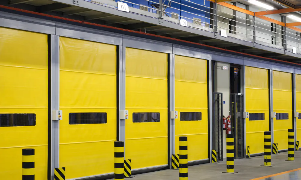
Warehouse Roll-Up and Sectional Doors
Recommended: BRC01 or BRC02
Distribution-center overhead doors running 250–400 cycles per day generate significant cumulative heat in the gear reducer. The BRC helical-bevel door gear reducer sustains ≥ 92 % efficiency at duty — reducing oil temperature rise by roughly 40 % compared with a worm-gear alternative at the same ratio — which translates directly to extended lubrication service intervals and longer gear surface life.
Cold-Storage Sliding and Hinged Doors
Recommended: BRC01, low-temperature option
Blast-freezer and controlled-atmosphere storage doors operate in ambient air as low as –22 °C. The EP door speed reducer low-temperature specification uses ISO VG 220 fully synthetic polyglycol gear oil rated to –40 °C pour point, eliminating the viscosity surge that causes cold-start bearing starvation in mineral-oil-filled units.
Logistics Bay and Dock-Leveler Doors
Recommended: BRC01 or BRC02
Loading-dock doors face high cycle counts combined with impact risk from forklift traffic. The BRC-series door gearbox reducer hollow-shaft output adapter eliminates the chain-drive transmission — a common maintenance point — by coupling directly to the door's torsion shaft. The tapered roller bearing output stage absorbs impact-induced shaft deflection that would fatigue the output shaft of a standard ball-bearing unit.
Fire-Rated and Smoke-Control Doors
Recommended: RV063, ratio ≥ 20 : 1
NFPA 80 requires powered fire doors to fail safe — closing and latching under gravity or spring force without electrical power. The RV-series worm door gear reducer at ratios of 20 : 1 and above provides mechanical self-locking that satisfies this requirement without an electromagnetic holding brake, simplifying the circuit design required for UL 325 system listing.
Food Processing and Pharmaceutical Cleanrooms
Recommended: BRC01 SS, IP65
Hygienic zones require drive hardware that resists daily alkaline or acid wash-down without corrosion of the gear housing or contamination of the food-contact environment. The stainless-steel housing variant of the EP door gear reducer carries IP65 ingress protection and is compatible with NSF/ANSI 169 wash-down requirements applicable in USDA-regulated processing facilities.
Aircraft Hangars and Auto Dealerships
Recommended: BRC02, hollow-shaft
Large-span bi-fold and sliding hangar doors can weigh 500–900 kg per leaf. The BRC02 door gearbox reducer at 60 : 1 or 80 : 1 provides up to 380 Nm continuous output torque — sufficient for most single-leaf hangar door installations — in a 13.2 kg package that fits existing header brackets without structural modification in the majority of retrofit projects.
8. Regulatory Framework — United States and Major Export Markets
Specifying a heavy-duty door gear reducer for a U.S. facility requires verifying conformance with the safety and product-liability standards enforced by the authority having jurisdiction (AHJ) at the installation site. The EP-series door gearbox reducer is designed to meet the following frameworks:
United States. UL 325 (Door, Drapery, Gate, Louver, and Window Operators) is the primary safety standard for powered door systems in the U.S. The EP controller interfaces with UL 325–listed entrapment-protection devices (monitored sensing edges, photo-eye beams). The gear reducer's current-monitoring output provides the secondary entrapment detection required by UL 325 without a separate force-limiting device. NEMA MG-1 motor efficiency categories apply to the drive motor; the paired brushless DC motor exceeds the IE4 super-premium threshold referenced in DOE motor rulemaking 10 CFR Part 431. NFPA 80 governs powered fire-door assemblies; the RV-series worm door speed reducer satisfies the mechanical fail-safe requirement. OSHA 29 CFR 1910.217 and ANSI/ASSE A10.44 apply at industrial workplaces.
European Union. The Machinery Regulation (EU) 2023/1230 — successor to the Machinery Directive 2006/42/EC, applicable from January 2027 — requires CE marking supported by a Declaration of Conformity and technical file. The Low Voltage Directive 2014/35/EU applies to the integrated drive controller. EN 13241 (Industrial, Commercial, and Garage Doors) defines the essential requirements for the complete door assembly; EN 60335-2-103 covers residential door operators. RoHS 3 (Directive 2015/863) compliance is confirmed for all EP-series assemblies.
Canada. CSA C22.2 No. 247 (Rotating Electrical Machines) and CSA C22.2 No. 0 apply to the motor and controller. ULC-S524 governs integration with fire-alarm systems for fire-rated door applications. The EP-series controller software conforms to IEC 62061 SIL 2 functional-safety requirements when paired with appropriate safety sensors, satisfying the risk-assessment obligations under provincial Occupational Health and Safety regulations.
Germany / DACH Region. DIN 18650 (Powered Pedestrian Doors) limits the closing force to 65 N and the kinetic energy at contact to 2 J. The adjustable deceleration profile of the EP controller can be set to comply with these limits without additional hardware. DGUV Regel 108-006 (formerly BGR 232) governs industrial-door safety at commercial workplaces. BRC-series gear reducers used on high-speed industrial doors also fall under EN 13241:2003+A2:2016 performance requirements for the door assembly as a whole.
Australia and New Zealand. AS/NZS 5010 (Automatic Doors) and the corresponding WHS regulations require risk-assessment documentation and guarding consistent with ISO 13857. The EP-series documentation package includes the force-torque data required for the risk-assessment record. Safe-torque-off (STO) signal output of the controller is compatible with AS 4024.3302 safety-circuit requirements.
ISO Global Standards. Manufacturing quality is governed by ISO 9001: 2015. Worm-gear load capacity is calculated to ISO 14521; helical-bevel gear capacity to ISO 6336. The overall gear reducer unit design conforms to ISO 23125 (Automatic Door Systems). These internationally recognized standards support product-liability documentation in any jurisdiction where the door gearbox reducer is installed.
9. Installation Steps — EP Door Gearbox Reducer
10. About Us
We are a specialist manufacturer of industrial gear reducers and integrated drive systems, with a dedicated engineering focus on door gearbox reducer technology for automatic door applications across North American and international markets. Our production facility holds ISO 9001: 2015 certification and operates a quality management system that tracks every unit from raw material incoming inspection through gear-tooth profile measurement, assembled-unit no-load and full-load test, and final outgoing audit — all traceable by serial number.
Our application engineers have accumulated more than twenty years of field experience specifying door gear reducers for distribution facilities, cold-storage operations, food-processing plants, and commercial building projects throughout the United States and Canada. When you provide a door weight, daily cycle count, available voltage, and site temperature range, we return a written gear-reducer recommendation.
WorkShop


11. Related Products — Complete the Drive System
Motors
We stock IEC and NEMA C-face standard induction motors pre-matched to the flange dimensions of the BLE and XLE gearbox series. IE3-efficiency three-phase and single-phase motor options are available, along with inverter-duty variants rated for full-torque operation at low speeds when controlled via VFD — a common requirement in agitator and conveyor applications.

Frequently Asked Questions
Editor: PXY