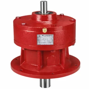
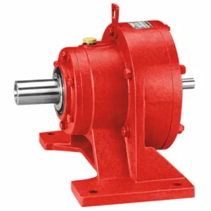
EP-BWE XWEシリーズ サイクロイドギアボックス
The EP-BWE XWE Series Cycloidal Gearbox is purpose-built to serve as both a primary drive reducer and a delayed-assembly unit across a broad spectrum of heavy industries. Whether deployed in chemical processing lines, cement conveyor systems, pharmaceutical manufacturing, or automated packaging operations, the EP-BWE XWE Cycloidal Gearbox maintains stable torque output with minimal vibration and remarkably quiet operation. Its transmission efficiency consistently exceeds 90%, making it an energy-conscious choice for facilities focused on long-term operational cost management.
Unlike standard involute gear reducers, the cycloidal disc mechanism distributes contact load across multiple pin engagements simultaneously. This multi-point load sharing is the fundamental reason why the EP-BWE XWE industrial cycloidal gearbox excels in shock-load environments — such as mining conveyors, metallurgical handling equipment, and construction machinery
1. Technical Performance Parameters of Cycloidal Gearbox
| パラメータ | 仕様 | 注記 |
|---|---|---|
| Transmission Efficiency | 94% – 96% | Average >90% under rated load |
| Single-Stage Ratio | 1:6 – 1:87 | Cycloidal pin gear engagement |
| Double-Stage Ratio | 1:99 – 1:7,569 | Stacked cycloidal stages |
| Noise Level (MAX) | 60 – 70 dB(A) | At rated speed and load |
| Temperature Rise (MAX) | 60°C | Above ambient under continuous operation |
| 振動 | ≤ 20 µm | Peak-to-peak at output shaft |
| 反発 | ≤ 60 Arc-min | Low backlash cycloidal reducer performance maintained over service life |
| Rated Power Range | 0.37 kW – 55 kW | Motor input |
| Max. Output Torque | 150 – 20,000 N·m | Model-dependent; see dimensional table |
| 潤滑 | GB 2# Lithium Grease / Mobilux EP 2 | Sealed housing; extended intervals |
| Mounting Configurations | Horizontal / Vertical / Double-Axle / Direct | Foot-mounted as standard on BWE/XWE series |
| IP Rating | IP54 (standard) | Higher ratings available on request |

EP-BWE Series — Mounting & Outline Dimensions (mm)
| モデル | H₀ (mm) | A (mm) | B (mm) | H (mm) | D (mm) | L-Dual (mm) | L₁-Dual (mm) | 体重(kg) |
|---|---|---|---|---|---|---|---|---|
| BWE 31 | 140 | 150 | 290 | 240 | 200 | 310 | 258 | 37 |
| BWE 42 | 120 | 195 | 330 | 275 | 240 | 384 | 326 | 75 |
| BWE 53 | 160 | 260 | 420 | 356 | 300 | 457 | 383 | 94 |
| BWE 63 | 200 | 335 | 430 | 425 | 340 | 519 | 447 | 148 |
| BWE 74 | 225 | 380 | 470 | 460 | 360 | 589 | 508 | 193 |
| BWE 84 | 250 | 440 | 530 | 529 | 430 | 633 | 552 | 270 |
| BWE 85 | 290 | 440 | 530 | 529 | 430 | 656 | 566 | 310 |
| BWE 95 | 290 | 560 | 620 | 614 | 500 | 745 | 655 | 485 |
| BWE 106 | 325 | 600 | 690 | 706 | 580 | 855 | 750 | 750 |
| BWE 116 | 420 | 810 | 880 | 883 | 710 | 1,066 | 958 | 1,232 |
| BWE 117 | 420 | 810 | 880 | 883 | 710 | 1,081 | 963 | — |
EP-XWE Series — Mounting & Outline Dimensions (mm)
| モデル | H₀ (mm) | A (mm) | B (mm) | H (mm) | D (mm) | L-Dual (mm) | L₁-Dual (mm) | 体重(kg) |
|---|---|---|---|---|---|---|---|---|
| XWE 130 | 160 | 250 | 390 | 356 | 300 | 414 | 367 | 82 |
| XWE 131 | 160 | 250 | 390 | 356 | 300 | 448 | 383 | 100 |
| XWE 141 | 200 | 380 | 400 | 425 | 340 | 519 | 447 | 153 |
| XWE 152 | 240 | 440 | 470 | 529 | 430 | 633 | 552 | 245 |
| XWE 153 | 290 | 440 | 470 | 529 | 430 | 666 | 566 | 265 |
| XWE 163 | 290 | 560 | 620 | 614 | 500 | 755 | 655 | 460 |
| XWE 174 | 325 | 600 | 690 | 706 | 580 | 860 | 750 | 710 |
| XWE 184 | 420 | 810 | 880 | 883 | 710 | 1,077 | 959 | 1,270 |
2. Five Key Product Advantages
What separates the EP-BWE XWE Series Cycloidal Gearbox from conventional speed reducers is not any single feature but a combination of engineering choices that compound into superior real-world performance. The following five advantages define why this unit is a preferred specification among procurement engineers across North America and beyond.
01 — Ultra-Wide Reduction Range
Single-stage ratios from 1:6 to 1:87 and double-stage ratios from 1:99 to 1:7,569 eliminate the need for external gearing stages, simplifying mechanical system design and reducing total drivetrain cost. Engineers gain precise control over output speed without sacrificing compactness.
02 — Verified High Efficiency
Transmission efficiency is rated at 94%–96%, well above the 70%–85% typical of worm gear reducers. This efficiency advantage translates directly into reduced motor load, lower energy bills, and less heat generated within the gearbox — extending lubricant life and prolonging service intervals significantly.
03 — Exceptional Shock Load Tolerance
The distributed contact across cycloidal disc lobes and ring pins means load is never concentrated at a single gear tooth pair. This architecture absorbs instantaneous shock loads that would fracture traditional gear teeth, making the EP-BWE XWE Series Cycloidal Gearbox ideal for conveyors, crushers, and intermittent-duty lifting equipment.
04 — Low Noise, Low Vibration
Operating noise is controlled to 60–70 dB(A) maximum, and shaft vibration is maintained below ±20 µm. These figures meet the requirements of noise-sensitive facilities such as pharmaceutical cleanrooms, food processing plants, and indoor logistics hubs where operator comfort and environmental compliance are statutory obligations.
05 — Compact Footprint, Long Service Life
The coaxial input-output shaft arrangement reduces overall installed length by more than two-thirds compared to equivalent two-stage cylindrical reducers. Quench-hardened bearing steel components and sealed lubrication extend maintenance intervals and service life, reducing total lifecycle cost for plant operators managing large equipment fleets.
3. Working Principle of the Cycloidal Pin Gear Reducer
At the mechanical core of the EP-BWE XWE サイクロイド減速機 lies a principle distinct from conventional involute gearing. The input shaft connects eccentrically to a bearing assembly that drives a cycloidal disc. As the input shaft rotates, the eccentric bearing causes the disc to orbit — not spin freely — within a fixed-pin ring gear. The disc's lobed perimeter engages sequentially with the ring pins distributed around the housing interior, and this rolling-without-sliding contact generates the reduction in rotational speed.
Because multiple lobes are in simultaneous mesh at any moment, torque is distributed across several contact points rather than concentrated at a single tooth pair. This is the mechanical origin of the EP-BWE XWE Cycloidal Gearbox's exceptional shock-load resistance. Roller pins embedded through the cycloidal disc transfer the orbital motion to an output disc, which converts epicyclic motion into smooth, continuous rotation at the output shaft — all without any relative sliding between the contact surfaces.
In the double-stage configuration of this series, a second cycloidal stage is stacked in series with the first, multiplying the speed reduction ratio exponentially. The coaxial arrangement of input and output shafts — a defining characteristic of cycloidal gearbox design — means the unit can be integrated directly inline with a motor shaft, eliminating the need for offset belt or chain drives. This inline architecture also improves dynamic balance, which in turn reduces bearing fatigue and extends the mean time between overhaul (MTBO) intervals.
The quench-and-temper heat treatment applied to all rotating components ensures surface hardness sufficient to resist abrasive wear while retaining a tough core that withstands impact without brittle fracture. GB 2# Lithium grease (or equivalent Mobilux EP 2) provides boundary lubrication at all cycloidal contact interfaces, maintaining a protective film even under the heavy preloads typical of high-ratio reduction applications.
4. Materials & Material Specifications
Material selection for the EP-BWE XWE サイクロイド歯車モーター drive series reflects decades of accumulated field data from heavy industrial deployments. Every material choice is deliberate — balancing hardness, toughness, machinability, and corrosion resistance against the specific stress environment each component must endure over a service life measured in years rather than months.
| 成分 | 材料 | Treatment | 関数 |
|---|---|---|---|
| ハウジング | Grade H Cast Iron | As-cast, precision machined | Structural rigidity and vibration damping |
| サイクロイド円盤 | GCr15 High-Carbon Chromium Bearing Steel | Quenching + Tempering | Primary torque transmission; hardened contact surface |
| Input Shaft | #45 High-Carbon Chromium Steel | Quenching + Tempering | Torsion and bending load carrier; keyway interface |
| 出力軸 | #45 High-Carbon Chromium Steel | Quenching + Tempering | Load transfer to driven equipment |
| Ring Pin | GCr15 Bearing Steel | Fine ground post-hardening | Cycloidal disc engagement; wear surface |
| 潤滑剤 | GB 2# Lithium Grease / Mobilux EP 2 | Sealed housing | Boundary film maintenance at all contact interfaces |
The combination of GCr15 bearing steel for the cycloidal disc and ring pins — both finished to fine-ground tolerances after heat treatment — creates a contact pair with surface hardness sufficient to resist abrasive wear while the tempered core maintains impact resistance. This dual characteristic (hard surface, tough core) is what enables the cycloidal reducer gearbox to tolerate the shock loads common in mining, construction, and heavy process industries without progressive tooth damage.

5. アプリケーションシナリオ
の cycloidal gearbox automation capability of this series, combined with its wide ratio range and multi-mounting flexibility, makes it one of the most broadly deployed drive units in industrial settings. The following sectors represent primary end-use environments where the EP-BWE XWE Series Cycloidal Gearbox delivers consistent, documented performance.
Chemical & Environmental Processing
Agitators, mixer drives, and wastewater treatment aeration equipment require continuous duty operation at stable low speeds. The sealed lubrication system and corrosion-resistant housing make the EP-BWE XWE Cycloidal Gearbox a natural fit for wet and chemical-laden environments.
Cement & Building Materials
Kiln ring drives, rotary coolers, and raw material handling conveyors operate under sustained high-torque, dusty conditions. The multi-point load contact of the cycloidal disc distributes stress evenly, preventing the localized tooth fatigue that limits standard helical gear reducers in these environments.
Food, Beverage & Pharmaceutical
Filling lines, packaging conveyors, and mixing vessels demand low-noise operation, easy cleaning access, and zero contamination risk. The low vibration (≤20 µm) and sealed bearing arrangement of this series meet GMP facility standards and FDA 21 CFR Part 110 production environment requirements applicable in the United States.
Textile & Printing Machinery
Warp beam drives, fabric tension rolls, and printing cylinder feeds require precise, repeatable speed ratio with minimal backlash drift over time. The ≤60 arc-min backlash specification of the EP-BWE XWE Cycloidal Gearbox holds even after extended operation, maintaining registration accuracy on high-speed printing lines and fabric tension systems.
Mining & Metallurgy
Ore conveyors, ball mill drives, and smelter trolley systems impose severe shock loads and continuous heavy-duty cycles. The quench-hardened GCr15 disc and ring pin assembly is specifically suited to absorbing these intermittent overloads while the cast iron housing damps structural vibration back to the machine frame.
Power Generation & Lifting Equipment
Cooling tower fan drives, sluice gate actuators, and overhead crane travel mechanisms operate in outdoor or semi-outdoor environments with wide temperature swings. The IP54-rated (standard) housing and high-temperature lithium grease formulation maintain performance across the full specified ambient temperature range without additional environmental enclosures.
6. Regulatory Compliance & International Standards
Procurement teams sourcing a cycloidal gearbox supplier USA or internationally must verify that the selected drive unit meets the regulatory framework applicable to their facility and target market. The EP-BWE XWE Series is engineered with reference to the following mandatory and voluntary standards:
| 地域/市場 | Standard / Regulation | Scope |
|---|---|---|
| アメリカ合衆国 | OSHA 29 CFR Part 1910 (Machine Guarding) | Requires adequate guarding on all rotating mechanical components; applicable to gearbox output shafts and couplings installed in U.S. facilities |
| アメリカ合衆国 | AGMA 9009-D02 (Alignment of Flexible Couplings) | Sets shaft alignment tolerances applicable during gearbox installation to prevent premature bearing failure |
| United States / Canada | ANSI/ABMA Standards (Bearing tolerances) | Internal bearing specifications align with ABMA dimensional and tolerance standards |
| 欧州連合 | EU Machinery Directive 2006/42/EC + CE Marking | Mandatory for drive components incorporated into machinery sold within the EU; CE declaration of conformity required |
| 欧州連合 | RoHS Directive 2011/65/EU | Restricts hazardous substances in electrical and electronic equipment, including gearbox-integrated motor units |
| Global (ISO) | ISO 9001:2015 (Quality Management) | Manufacturing process quality assurance framework; ensures documented production controls |
| Global (ISO) | ISO 6336 (Gear Load Capacity) | Design basis for tooth and contact stress calculations in cycloidal disc geometry |
| Australia / NZ | AS 4024 (Safety of Machinery) | Governs rotating component safeguarding requirements in Australian industrial installations |
| 日本 | JIS B 1701 (Cylindrical Gears) | Japanese Industrial Standard for gear tolerance and surface finish applicable to drive components exported to Japan |
Facilities operating in the United States food and pharmaceutical sectors should additionally verify compliance with FDA 21 CFR Part 110 (Current Good Manufacturing Practice in Manufacturing, Packing, or Holding Human Food) when specifying this unit for direct-contact or near-contact food production lines. The sealed lubrication system and cast-iron housing support compliance but the end-user bears responsibility for site-specific risk assessment and hygiene documentation.
7. 当社について
We are a specialized manufacturer of industrial power transmission solutions with deep engineering roots in cycloidal and planetary gear technology. Our engineering team carries decades of cumulative experience in cycloidal gearbox design — from entry-level compact units used in servo positioning systems to large-frame double-stage foot-mounted models specified for continuous-duty mining conveyors. We support cycloidal gearbox custom order manufacturer requirements, working from customer-supplied CAD drawings or application specifications to produce non-standard ratio, shaft configuration, or housing material variants.
Our quality system is aligned with ISO 9001:2015, and outgoing inspection includes dimensional verification, backlash measurement, efficiency run-in testing, and noise/vibration assessment prior to shipment.
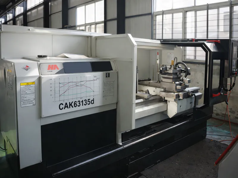
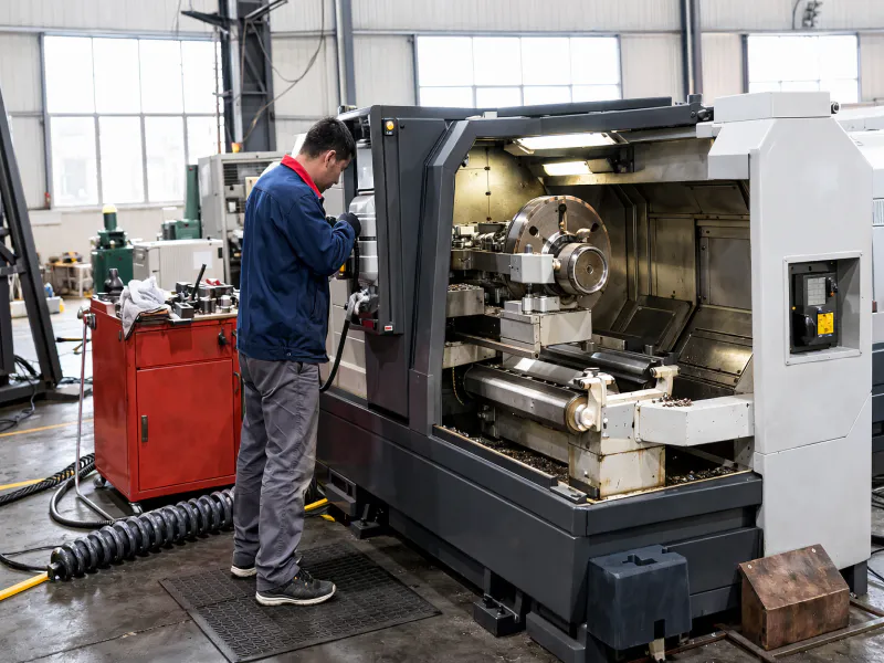
ワークショップ


8. Installation & Commissioning Guidance
Correct installation is as critical to long-term gearbox performance as the unit's own engineering. The following installation sequence applies to the EP-BWE XWE double-stage foot-mounted configuration and should be followed in full during initial commissioning as well as after any scheduled overhaul.
Before beginning, verify that the motor frame dimensions, shaft diameter, and keyway dimensions are dimensionally compatible with the gearbox input interface. Clean all mating surfaces — motor locating boss, input shaft, and reducer socket — with appropriate solvent to remove residual rust preventative coating. This step ensures full concentricity at the input interface, which is the primary driver of early bearing failure when omitted.
When connecting the motor to the gearbox, ensure the output shaft of the reducer and the motor input shaft are coaxial and that the outer flanges are parallel. Never use a hammer to drive shaft connections — impact loads applied axially or radially will damage internal bearings and cycloidal disc pin bores. Use only the specified tightening sequence: install mounting bolts finger-tight at opposing positions before torquing to specification using a calibrated torque wrench, following the cross-pattern sequence shown in the installation manual. The motor shaft keyway must be perpendicular to the tightening bolt axis before the final clamp-ring engagement.
After installation, perform a no-load run of at least 30 minutes and verify that operating temperature rise, noise level, and shaft vibration fall within the specified limits before applying process load. Any anomalous temperature rise above 60°C over ambient, or noise above 70 dB(A), should be investigated before full-load operation commences.

Related Products & System Compatibility
Our manufacturing capability extends beyond the サイクロイドギアボックス itself. For customers building complete drive system assemblies, we supply compatible input and output components designed for direct integration — eliminating the adapter and interface engineering effort typically required when sourcing from multiple vendors.
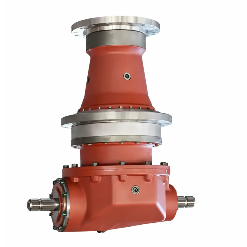
遊星歯車機構
精密なエンジニアリングと堅牢な構造で製造された当社のギアボックスは、信頼性の高いトルク増幅、最小限のバックラッシュ、そして強化された耐荷重性能を実現します。
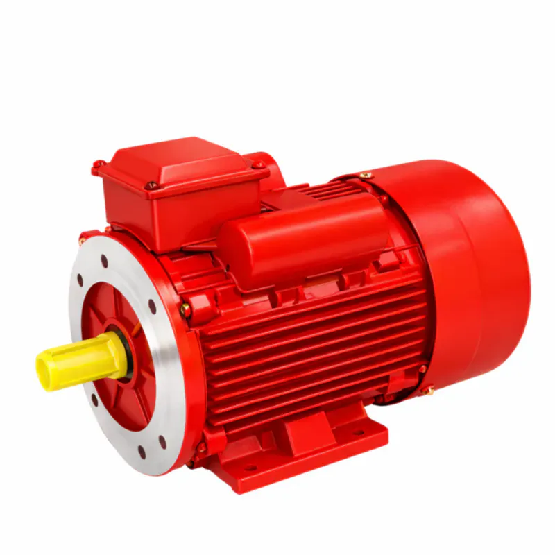
駆動モーター
当社では、BLEおよびXLEギアボックスシリーズのフランジ寸法に適合するよう事前に調整された、IECおよびNEMA C面規格の誘導モーターを取り揃えています。IE3効率の三相モーターと単相モーターのオプションに加え、VFD制御時に低速でフルトルク運転が可能なインバーター対応モデルもご用意しています。これは、攪拌機やコンベア用途でよく求められる要件です。
よくある質問
編集者: PXY