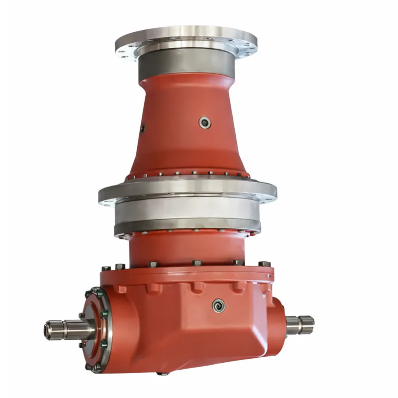
EP-Cycloidal Pinwheel Reducer Gearbox
The EP-Cycloidal Pinwheel Reducer Gearbox is a precision-engineered cycloidal speed reducer that operates on the K-H-V planetary transmission principle, using a cycloidal disc meshing with needle pins to achieve gear ratios from 6:1 up to 658,503:1 across up to three stages. It accepts input power from 0.09 kW to 173 kW, delivers output torque from 20 N·m to 60,800 N·m, and achieves single-stage mechanical efficiency of 90%–95% — while maintaining an extremely compact footprint suited to conveyor drives, lifting machinery, and heavy industrial applications.
Industrial Power Transmission
EP-Cycloidal Pinwheel Reducer Gearbox
A high-performance cycloidal speed reducer engineered for demanding industrial environments — delivering high torque output, exceptional overload resilience, and ultra-compact form in a single reliable unit.
1. Technical Specifications of Cycloidal Pinwheel Reducer Gearbox
The table below presents the core engineering parameters for the EP-Cycloidal Pinwheel Reducer Gearbox series. All figures are measured at rated conditions (input speed 1,450 RPM, ambient temperature 20 °C) and comply with ANSI/AGMA 6014-B08 and ISO 1328-1:2013 standards for industrial gear reducers.
| Parameter | Specification | Standard / Note |
|---|---|---|
| Gear Reduction Type | Cycloidal pinwheel (K-H-V planetary) | JB/T 2982 / ISO 6336 |
| Single-stage Ratio Range | 6:1 – 87:1 | Standard stock ratios |
| Two-stage Ratio Range | 99:1 – 7,569:1 | XWD / XLD series |
| Three-stage Ratio Range | 5,841:1 – 658,503:1 | Triple-reduction configurations |
| Rated Output Torque | 20 N·m – 60,800 N·m | Varies by frame size XW8075–XW8265 |
| Peak Overload Torque | Up to 500% of rated (momentary) | Shock load resistant design |
| Input Speed Range | 750 – 1,500 RPM | Standard; VFD use available |
| Output Speed Range | 0.3 – 136 RPM | Depending on ratio selected |
| Input Power Range | 0.09 kW – 173 kW | IEC / NEMA motor frames |
| Mechanical Efficiency (Single Stage) | 90% – 95% | Rolling mesh, measured at full rated load |
| Mechanical Efficiency (Double Stage) | ~85% (approx.) | Two-stage compounded loss |
| Ambient Operating Temperature | −40 °C to +40 °C | Standard lubricant (40# / 50# oil) |
| Max. Oil Sump Temperature Rise | ≤ 60 °C above ambient | At rated load and rated speed |
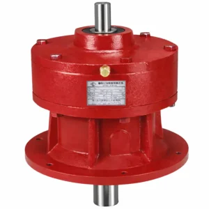
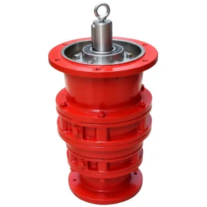
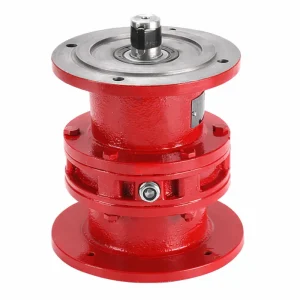
| Mounting Position | Horizontal (XW) / Vertical (XL) | Foot or flange mount |
| Output Shaft Type | Solid shaft / Hollow shaft | Direct-joint (D) variant available |
| Output / Input Shaft Key Type | Flat key per GB/T 1096 | Standard common flat key dimensions |
| Noise Level (Typical) | < 70 dB(A) at 1 m | Multi-tooth simultaneous engagement; ISO 1680 |
| Lubrication — Models 8075–8155 | Grease (horizontal & vertical) | Models ≤8155A–C also grease-lubricated |
| Lubrication — Models 8160–8185 | Oil bath + plunger pump | Models 8160A–8227A: oil bath + gear pump |
| Lubrication — Models 8190–8275 | Gear pump (forced circulation) | 70# or 90# EP gear oil recommended |
| Protection Class | IP54 standard; IP65 optional | IEC 60529 |
| Quality Standard | ISO 9001:2015 | Full QMS documentation available |
Service Conditions
Applicable to continuous 24-hour working systems. Allows both forward and reverse operation without restriction.
Output and input shaft extension keys shall conform to GB/T 1096 common flat key type and size specifications.
The horizontal double-shaft output model shall be installed and operated in a horizontal position. Inclined mounting requires manufacturer approval.
The vertical reducer output shaft shall be directed vertically downward. Models below 8155 are grease-lubricated and may also be installed horizontally.
Lubrication Method by Model (Horizontal / Vertical)
| Machine Model | Horizontal | Vertical | Machine Model (A/C variants) | Horizontal | Vertical |
|---|---|---|---|---|---|
| 8075 – 8155 | Grease | Grease | 8075A – 8145C | Grease | Grease |
| 8160 – 8185 | Oil bath | Plunger pump | 8160A – 8227A | Oil bath | Gear pump |
| 8190 – 8275 | Gear pump | Gear pump | — | — | — |
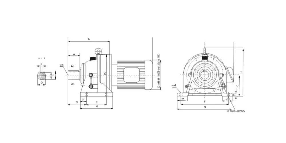
EP Series — Cycloidal Pinwheel Reducer Gearbox (All Models 8075–8265)
All dimensions in millimeters (mm). Weight in kg. Output shaft dimensions: D = shaft diameter; e = shaft length; b = key width; t = keyway depth; h = overall shaft+hub length; sxm = thread spec. Mounting hole: n-d = number × bolt circle diameter.
| Cycloidal Pinwheel Reducer Gearbox Model | A | C | DC | E | F | M | N | G | P | H | R | V | n-d | Output / 输出 | Weight (kg) | |||||
|---|---|---|---|---|---|---|---|---|---|---|---|---|---|---|---|---|---|---|---|---|
| D | e | b | t | h | sxm | |||||||||||||||
| EP-XW8075 | 92 | 80 | 110 | 60 | 120 | 84 | 144 | 41 | 12 | 138 | 10 | 35 | 4-φ9 | 14 | 25 | 5 | 11 | 16 | — | 2 |
| EP-XW8085 | 98 | 80 | 110 | 60 | 120 | 84 | 144 | 47 | 12 | 138 | 10 | 35 | 4-φ9 | 18 | 30 | 6 | 14.5 | 20.5 | — | 2 |
| EP-XW8095 | 142 | 100 | 150 | 90 | 150 | 130 | 180 | 60 | 15 | 207 | 12 | 40 | 4-φ11 | 28 | 35 | 8 | 24 | 31 | — | 8 |
| EP-XW8105 | 156 | 100 | 150 | 90 | 150 | 130 | 180 | 65 | 15 | 207 | 12 | 40 | 4-φ11 | 28 | 45 | 8 | 24 | 31 | — | 13 |
| EP-XW8115 | 192 | 120 | 204 | 115 | 190 | 155 | 230 | 82 | 20 | 257 | 15 | 55 | 4-φ14 | 38 | 55 | 10 | 33 | 41 | — | 27 |
| EP-XW8125 | 192 | 140 | 204 | 115 | 190 | 155 | 230 | 82 | 20 | 277 | 15 | 60 | 4-φ14 | 38 | 55 | 10 | 33 | 41 | — | 28 |
| EP-XW8130 | 240 | 150 | 230 | 145 | 290 | 195 | 330 | 100 | 25 | 300 | 22 | 65 | 4-φ18 | 50 | 70 | 14 | 44.5 | 53.5 | M10×18 | 43 |
| EP-XW8135 | 240 | 150 | 230 | 145 | 290 | 195 | 330 | 100 | 25 | 300 | 22 | 65 | 4-φ18 | 50 | 70 | 14 | 44.5 | 53.5 | M10×18 | 48 |
| EP-XW8145 | 260 | 150 | 230 | 145 | 290 | 195 | 330 | 120 | 25 | 300 | 22 | 65 | 4-φ18 | 50 | 90 | 14 | 44.5 | 53.5 | M10×18 | 49 |
| EP-XW8155 | 260 | 160 | 230 | 145 | 290 | 195 | 330 | 120 | 25 | 310 | 22 | 70 | 4-φ18 | 50 | 90 | 14 | 44.5 | 53.5 | M10×18 | 56 |
| EP-XW8160 | 308 | 160 | 300 | 150 | 370 | 238 | 410 | 139 | — | 356 | 25 | 75 | 4-φ18 | 60 | 90 | 18 | 53 | 64 | M10×18 | 85 |
| EP-XW8165 | 308 | 160 | 300 | 150 | 370 | 238 | 410 | 139 | — | 356 | 25 | 75 | 4-φ18 | 60 | 90 | 18 | 53 | 64 | M10×18 | 85 |
| EP-XW8170 | 352 | 200 | 340 | 275 | 380 | 335 | 430 | 125 | — | 425 | 30 | 80 | 4-φ22 | 70 | 90 | 20 | 62.5 | 74.5 | M12×24 | 121 |
| EP-XW8175 | 352 | 200 | 340 | 275 | 380 | 335 | 430 | 125 | — | 425 | 30 | 80 | 4-φ22 | 70 | 90 | 20 | 62.5 | 74.5 | M12×24 | 121 |
| EP-XW8180 | 389 | 220 | 370 | 320 | 420 | 380 | 470 | 145 | — | 460 | 30 | 82 | 4-φ22 | 80 | 110 | 22 | 71 | 85 | M12×24 | 153 |
| EP-XW8185 | 389 | 220 | 370 | 320 | 420 | 380 | 470 | 145 | — | 460 | 30 | 85 | 4-φ22 | 80 | 110 | 22 | 71 | 85 | M12×24 | 153 |
| EP-XW8190 | 465 | 250 | 430 | 380 | 480 | 440 | 530 | 170 | — | 529 | 35 | 90 | 4-φ26 | 95 | 135 | 25 | 86 | 100 | M20×34 | 226 |
| EP-XW8195 | 465 | 250 | 430 | 380 | 480 | 440 | 530 | 170 | — | 529 | 35 | 90 | 4-φ26 | 95 | 135 | 25 | 86 | 100 | M20×34 | 226 |
| EP-XW8205 | 502 | 250 | 448 | 360 | 440 | 440 | 530 | 215 | — | 530 | 35 | 100 | 4-φ26 | 100 | 165 | 28 | 90 | 106 | M20×34 | 253 |
| EP-XW8215 | 526 | 265 | 485 | 395 | 480 | 475 | 580 | 210 | — | 575 | 40 | 110 | 4-φ33 | 110 | 165 | 28 | 100 | 116 | M20×34 | — |
| EP-XW8225 | 566 | 280 | 526 | 440 | 540 | 520 | 620 | 230 | — | 610 | 40 | 115 | 4-φ33 | 120 | 165 | 32 | 109 | 127 | M20×34 | — |
| EP-XW8235 | 628 | 300 | 562 | 460 | 580 | 560 | 670 | 260 | — | 667 | 45 | 120 | 4-φ39 | 130 | 200 | 32 | 119 | 137 | M24×41 | — |
| EP-XW8245 | 657 | 335 | 614 | 480 | 630 | 580 | 720 | 263 | — | 729 | 45 | 128 | 4-φ39 | 140 | 200 | 36 | 128 | 148 | M24×41 | — |
| EP-XW8255 | 775 | 375 | 670 | 520 | 670 | 630 | 780 | 320 | — | 815 | 50 | 140 | 4-φ39 | 160 | 240 | 40 | 147 | 169 | M24×41 | — |
| EP-XW8265 | 892 | 400 | 736 | 590 | 770 | 700 | 880 | 390 | — | 874 | 55 | 160 | 4-φ45 | 170 | 300 | 40 | 157 | 179 | M30×49 | — |
All dimensions nominal. Tolerances per ISO 286-1 (shaft fits) and ISO 2768-m (general). Detailed CAD drawings and 3D STEP files available on request for OEM integration and custom mounting design.
2. Five Key Technical Facts of Cycloidal Pinwheel Reducer Gearbox
3. 5 Key Product Advantages of Cycloidal Pinwheel Reducer Gearbox
Compared to a standard helical or worm gear reducer — and even when evaluated in the context of a cycloidal reducer vs planetary gearbox scenario — the EP-Cycloidal Pinwheel Reducer Gearbox consistently stands out across five engineering dimensions that matter most to procurement engineers and plant managers in the United States and globally.
With a single-stage reduction spanning 6:1 to 87:1, the EP unit eliminates the need for multi-gear intermediate stages that are typical in traditional cylindrical gear trains. This means fewer moving parts, reduced assembly time on the production line, and a more compact final machine footprint. When two or three stages are combined, ratios extend to 658,503:1 — a figure virtually unattainable through involute spur or bevel gear configurations of comparable size. This ratio range makes the EP series an ideal heavy duty cycloidal reducer gearbox for scenarios that demand extreme torque multiplication without sacrificing machine floor space.
Single-stage mechanical efficiency consistently exceeds 93%, while double-stage configurations retain approximately 86% efficiency — figures that exceed most worm gear reducers at comparable ratios, where efficiencies can drop to 60–80%. This translates directly into energy cost savings and reduced heat generation at the gearbox housing. In high-cycle industrial automation, conveyor drives, and material handling installations, the lifetime energy savings justify the capital investment many times over. The rolling contact between the cycloidal disc and needle pins minimizes sliding friction, which is the primary cause of heat and wear in conventional gear meshes.
Because the cycloidal disc engages multiple pins simultaneously — typically 60–66% of the available pin teeth are in contact at any moment — the transmitted force is shared across a large contact area. This multi-point load sharing gives the EP-Cycloidal Pinwheel Reducer Gearbox a rated service factor up to 1.25× higher than AGMA recommendations for conventional reducers of the same size, and a peak overload capacity reaching 500% of rated torque for brief shock events. This makes the unit highly resistant to the sudden load reversals common in presses, mixers, crane hoists, and mining conveyor drives.
The cycloidal pinwheel's inherent balance — achieved through dual offset discs mounted 180° apart — keeps vibration low without requiring external counterweights. This compact engineering allows the EP Cycloidal Pinwheel Reducer Gearbox to replace two-stage or three-stage cylindrical gear trains in a housing up to 40% smaller by volume. The oil pool lubrication system (standard for horizontal mounting) requires attention only every 3–6 months under normal conditions, and the straightforward construction — with no hypoid bevels or complex sun-planet arrangements — means the unit can be overhauled in the field without specialized tooling. This directly reduces planned maintenance downtime on the production floor.
The EP series Cycloidal Pinwheel Reducer Gearbox accepts input from standard IEC and NEMA frame motors ranging from 0.04 kW up to 75 kW, including variable-frequency drives (VFDs), brake motors, and explosion-proof motors conforming to ATEX / IECEx Zone 1 requirements. Both horizontal (XW-type) and vertical (XL-type) foot and flange mounting configurations are available as standard, minimising engineering integration time. Direct-coupled and hollow-shaft output options further expand the range of conveyor, agitator, and rotary drive installations that can be served without a custom adapter. This flexibility positions the EP unit as an ideal cycloidal pinwheel gearbox for automation USA and North American industrial OEM procurement programs.
4. How the Cycloidal Pinwheel Reducer Gearbox Works
Understanding how does a cycloidal gearbox work is essential for engineers evaluating it against planetary or worm alternatives. The EP-Cycloidal Pinwheel Reducer Gearbox applies the K-H-V planetary transmission principle — a mechanism that converts high-speed rotary input into low-speed, high-torque output through the eccentric orbital motion of a precision-ground cycloidal disc.
The input shaft carries a double-eccentric sleeve mounted at 180° offset. Two swivel-arm roller bearings installed on this sleeve form the H-mechanism. As the input shaft rotates, the eccentric sleeve causes the cycloidal disc to execute a wobbling orbital path — not a free spin — around the housing axis. This eccentric motion is the driving force behind the entire reduction mechanism and is why the unit operates with inherently smooth, rolling contact rather than sliding tooth engagement.
The cycloidal disc has an external lobed profile ground to a precise cycloidal curve. This disc meshes continuously with a ring of hardened needle pins fixed to the housing. Because the number of lobes on the cycloidal disc is always exactly one fewer than the number of needle pins in the housing, one full orbit of the disc produces a single-tooth rotation of the disc relative to the housing. This one-tooth-difference principle is what generates the gear reduction. At any instant, more than half of the needle pins are simultaneously engaged, distributing force uniformly and dramatically reducing contact stress on each individual pin.
The cycloidal disc contains a series of equidistant holes. Output drive pins — or output rollers — pass through these holes and connect directly to the output flange or shaft. As the cycloidal disc orbits, the drive pins translate only the pure rotational component of the disc's motion to the output shaft, filtering out the eccentric wobble. The result is a clean, low-vibration, high-torque rotation at the output end. The dual-disc configuration (two discs phased 180° apart) cancels the remaining dynamic imbalance, producing exceptionally smooth running at both low and moderate speeds.
For multi-stage configurations, the output shaft of the first stage becomes the input of the second stage cycloidal assembly, compounding the ratios multiplicatively. A two-stage EP Cycloidal Pinwheel Reducer Gearbox can therefore achieve ratios of 99:1 to 7,569:1 — and three stages push this to a maximum of 658,503:1 — while the overall envelope grows only modestly compared to the single-stage version. This ratio stacking without proportional size growth is what separates the cycloidal pinwheel speed reducer from most alternative technologies in applications where space and torque density are simultaneously constrained.

5. Material Composition & Construction
The EP-Cycloidal Pinwheel Reducer Gearbox is built from a carefully selected combination of high-grade metallurgical materials, each chosen to maximize durability, fatigue resistance, and dimensional stability under continuous industrial operation. Material choices align with ASTM, DIN, and ISO material standards to ensure global supply-chain traceability and consistent mechanical properties across production batches.
| Component | Material | Surface Treatment | Key Property |
|---|---|---|---|
| Cycloidal Disc (Pinwheel) | GCr15 high-carbon chromium bearing steel | Quench + temper, HRC 58–62 | High contact fatigue strength, wear resistance |
| Needle Pin (Pin Gear) | GCr15 bearing steel | Through-hardened, ground finish Ra 0.4 | Rolling fatigue endurance, precise geometry |
| Input Eccentric Shaft | 20CrMnTi alloy carburising steel | Case carburised + quenched, HRC 56–62 | Torsional strength, surface wear resistance |
| Output Shaft | 45# medium-carbon steel or 42CrMo alloy steel | Induction hardened bearing seats, HRC 48–54 | High tensile strength, keyway integrity |
| Housing / Casing | HT250 grey cast iron (standard); nodular iron QT500-7 (heavy-duty) | Shot-blasted, epoxy primer + topcoat | Dimensional rigidity, vibration damping |
| Swivel Arm / Crank Bearings | High-grade cylindrical roller bearings (GCr15) | Factory-pre-greased, sealed | Long L10 service life under radial loading |
| Output Drive Pins & Rollers | Bearing steel, precision ground | Through-hardened | Smooth torque transfer, minimal backlash |
| Seal System | NBR (standard) / FKM Viton (high-temperature option) | Double-lip shaft seal | IP54 / IP65 oil retention, contaminant exclusion |
6. Application Scenarios
The EP-Cycloidal Pinwheel Reducer Gearbox serves a broad spectrum of industrial sectors. Its combination of high torque density, broad ratio range, and shock load tolerance makes it one of the most versatile cycloidal drive solutions available to industrial buyers in the United States and across international markets. Below are the primary application categories where the EP series Cycloidal Pinwheel Reducer Gearbox delivers measurable performance advantages.
As a cycloidal pinwheel reducer for conveyor systems USA, the EP series drives belt conveyors, chain conveyors, screw conveyors, and bucket elevators in mining, aggregate, and food processing plants. Its shock load resilience handles start-stop operations and varying load profiles without premature bearing fatigue. High reduction ratios in a compact housing reduce conveyor drive head length, freeing valuable plant floor space.
For cycloidal reducer gearbox for robotics US supplier applications, the EP Cycloidal Pinwheel Reducer Gearbox's low backlash and smooth torque output are critical. It is used in articulated robot joints, SCARA arm pivot drives, collaborative robot (cobot) axes, and CNC rotary table indexing. The high ratio in a single stage reduces the total number of gearbox stages required, improving positional repeatability and reducing backlash accumulation across multi-joint robot arm designs.
In chemical reactors, pharmaceutical batch mixers, food dough kneaders, and cement paste agitators, the EP Series Cycloidal Pinwheel Reducer Gearbox maintains consistent torque output across a wide viscosity range. Its ability to sustain overload events of up to 500% rated torque — common during mixer start-up with a full load — prevents shaft breakage and gearbox seizure that affects competing worm reducers at equivalent power levels. The sealed IP54 / IP65 housing resists washdown and chemical ingress in food and pharma environments.
In electric shovel crowd drives, ball mill feed conveyors, rolling mill table drives, and sintering machine pallets, the high torque cycloidal reducer must withstand continuous impact loading and abrasive dust environments. The EP Cycloidal Pinwheel Reducer Gearbox's cast iron / ductile iron housing withstands the vibration levels common in these settings, and the multi-pin load sharing reduces per-pin Hertzian contact stress to levels that enable service intervals beyond 20,000 hours under rated conditions.
The EP Cycloidal Pinwheel Reducer Gearbox is specified for hoist winches, tower crane slewing rings, concrete mixer drums, and construction elevator drives. In these safety-critical environments, the unit's inherent braking characteristic — the cycloidal disc naturally resists back-driving under gravity load — provides a passive mechanical safety function independent of the motor brake. This back-driving resistance is a key reason why plant engineers in the USA select an industrial cycloidal gearbox manufacturer USA unit over a worm gear reducer in hoist applications.
Slow-speed, high-torque drives for screw press dewatering units, sludge thickeners, clarifier rakes, and biogas mixer paddles are a natural fit for the cycloid gear reducer's output speed range of 0.3–136 RPM. Water treatment plant operators across the United States value the unit's sealed construction, its resistance to moisture intrusion, and the low maintenance requirement — all of which reduce total cost of ownership in remote or outdoor installation environments where service access is limited.
7. Fault Analysis & Maintenance Guide
After extended operation under load, wear and oil leakage are the two most common issues encountered with the EP-Cycloidal Pinwheel Reducer Gearbox. Understanding these failure modes and their proven remedies helps plant maintenance engineers minimize unplanned downtime and extend equipment service life.
Common Wear Failure Locations
Includes wear of the housing bearing bore, the internal bearing chamber of the casing, and the transmission bearing housing seats. This is the most frequently reported structural wear location in long-running units.
The shaft head and keyway areas are the primary worn zones on the gear shaft. Repeated start-stop and reversing cycles concentrate fretting wear at these transitions, particularly where keyway fit tolerances are marginal.
The bearing seats on the transmission shaft are subject to fretting corrosion and dimensional creep under oscillating loads, leading to loss of interference fit and eventual housing bore damage if not addressed promptly.
Leakage at mating housing surfaces occurs when gasket compression relaxes over time or when housing distortion opens micro-gaps at the split lines. This is an operational nuisance that also accelerates lubricant depletion.
Wear Repair Solutions
Traditional repair methods include weld build-up and brush plating. However, both carry known risks: high-temperature weld repair introduces thermal stress that may cause bending or fracture; brush plating is limited by coating thickness and is prone to delamination. Contemporary practice in the West — and now widely adopted in US industrial maintenance — uses high-performance polymer composites for on-site repair. These materials offer superior adhesion, excellent compressive strength, and the ability to absorb shock and vibration. Critically, they eliminate the metal-on-metal "hard-to-hard" contact that causes re-wear, and repair thickness is unrestricted. Repairs can be performed without full disassembly, greatly reducing planned downtime.
Oil Leakage Prevention & Solutions
Internal pressure exceeding atmospheric pressure is a primary driver of seal leakage. The standard vent hole can become blocked by oil contamination or dust. The recommended solution is an oil-cup type vent cap with a 6 mm vent diameter, fitted on a 6 mm thick inspection cover plate. This allows pressure equalisation and eliminates the need to open the manhole cover during refuelling — reducing leakage opportunity significantly.
Excess lubricating oil thrown onto bearings by gear rotation must return to the sump without pooling at the shaft seal. The recommended approach is to machine an oil return groove in the center of the lower bearing pad — inclined toward the machine interior — combined with a gap at the straight port of the end cover, allowing excess oil to drain back to the oil pool along a defined flow path rather than accumulating at the lip seal.
For active leaks, polymer composite sealants with superior oil resistance and 350% elongation can be applied on-site without full disassembly. These materials flex with the vibrating housing surface, preventing re-leakage under dynamic operating conditions — a solution that avoids the time and labour of a conventional gasket replacement procedure.

8. Regulatory Compliance & Industry Standards
Industrial buyers performing due diligence for gearbox procurement — whether sourcing a cycloidal pinwheel reducer gearbox supplier USA or evaluating OEM supply chains globally — must confirm that the selected reducer meets applicable codes and certifications. The EP-Cycloidal Pinwheel Reducer Gearbox is designed and produced against the following standards and directives.
| Region / Body | Applicable Standard or Directive | Scope |
|---|---|---|
| United States | ANSI/AGMA 6014-B08, AGMA 6010-F97 | Enclosed helical, herringbone, and cycloidal gear reducer rating standards |
| United States — Workplace Safety | OSHA 29 CFR 1910.217 (machine guarding); NFPA 70 (NEC) for motor wiring | Gearbox installation, coupling guard requirements, electrical interface |
| European Union | CE Marking per EU Machinery Directive 2006/42/EC | Mechanical safety, essential health and safety requirements for drive components |
| European Union — Hazardous Areas | ATEX Directive 2014/34/EU (Zone 1, 2, 21, 22) | Explosion-proof motor pairing with YB-series motors available |
| International — Quality | ISO 9001:2015 Quality Management System | Full QMS certification covering design, manufacturing, and inspection |
| International — Gear Geometry | ISO 1328-1:2013 (gear accuracy), ISO 6336 (gear load capacity) | Cycloidal disc profile accuracy and rated load calculation basis |
| China — Domestic Standard | JB/T 2982 Cycloidal Pinwheel Reducer standard | Dimensional interchangeability with Sumitomo Cyclo-type frames |
| Food & Pharma (USA) | FDA 21 CFR Part 178 (incidental food contact lubricants) | H1-grade lubricant option available for food-grade installations |
| Environmental (EU & Global) | RoHS 2 Directive 2011/65/EU | Restriction of hazardous substances in manufacturing materials |
| Australia / New Zealand | AS 4024.1 (machinery safety); AS/NZS 3000 (wiring rules) | Installation compliance for Oceania markets |
Note: Regulatory compliance documentation, including CE Declaration of Conformity, ISO 9001 certificate, and ATEX motor pairing certificates, is available upon request for procurement due diligence and customs clearance purposes.
9. About Us
We are a dedicated industrial power transmission manufacturer with over decades of focused production experience in cycloidal speed reducers, planetary gearboxes, and related drive components. Our engineering team includes mechanical engineers specialising in gear geometry, tribology, and fatigue analysis, alongside a quality assurance department that operates under a fully certified ISO 9001:2015 QMS. Every EP-Cycloidal Pinwheel Reducer Gearbox that leaves our production facility has been individually tested on an automated test bench that verifies input-to-output efficiency, vibration signature, and oil tightness before packing. We hold CE certification for the full EP Cycloidal Pinwheel Reducer Gearbox range and can supply ATEX-compliant motor-and-reducer assemblies for hazardous-area installations.
Our manufacturing process integrates CNC gear grinding machines calibrated to ISO 1328-1 Grade 5 accuracy, coordinate measuring machines (CMM) for 100% dimensional verification of cycloidal discs, and automated assembly lines equipped with torque-controlled fastening tools.
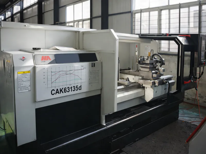
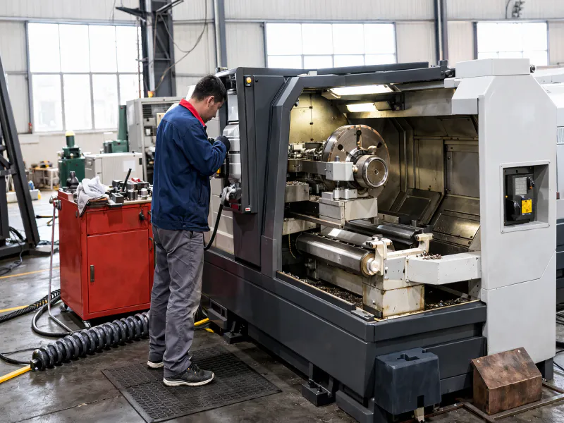
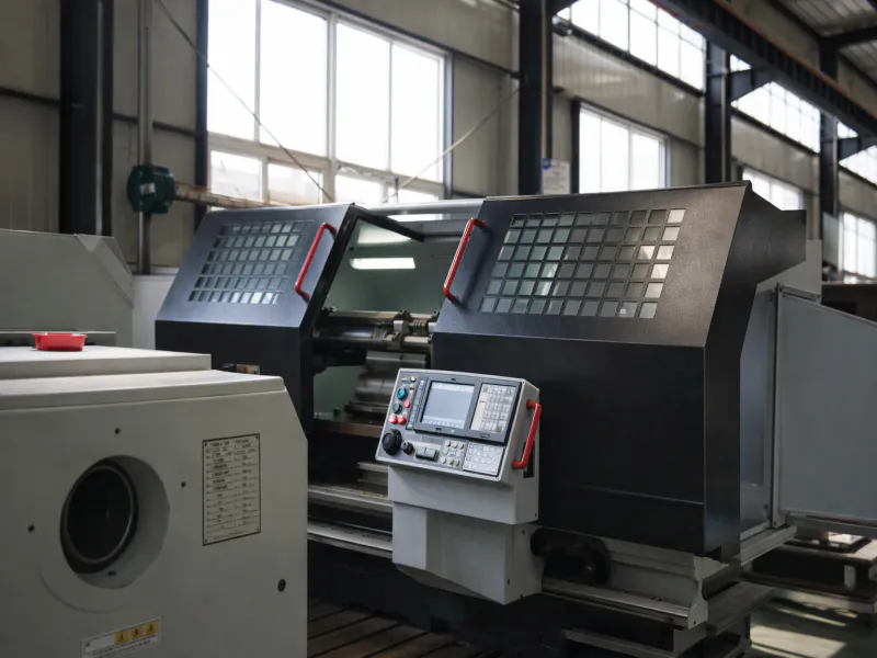
WorkShop


10. Related Products & System Compatibility
A complete power transmission system is more than the gearbox alone. We manufacture and supply compatible drive components that integrate directly with the EP-Cycloidal Pinwheel Reducer Gearbox, enabling one-stop sourcing and guaranteed system compatibility. This eliminates the integration risk and lead-time friction that comes from assembling drives from multiple, uncoordinated suppliers.
Planetary Gearbox
Built with precision engineering and robust construction, our gearboxes deliver dependable torque multiplication, minimized backlash, and enhanced load capacity.
Drive Motors
We stock IEC and NEMA C-face standard induction motors pre-matched to the flange dimensions of the BLE and XLE gearbox series. IE3-efficiency three-phase and single-phase motor options are available, along with inverter-duty variants rated for full-torque operation at low speeds when controlled via VFD — a common requirement in agitator and conveyor applications.
FAQA
Q1. How does a cycloidal pinwheel reducer gearbox work differently from a standard planetary gearbox, and which should I choose for my automation line?
Q2. Which industries in the United States most commonly use cycloidal pinwheel gearboxes for automation, and what are the typical performance requirements in those sectors?
Q3. Is there a cycloidal pinwheel reducer gearbox diagram available, and what do the model number characters mean for the EP Cycloidal Pinwheel Reducer Gearbox?
Q4. What gear ratio should I select for a conveyor drive application running at 1,450 RPM motor input and needing 12 RPM at the output shaft?
Q5. How often does the cycloidal pinwheel reducer gearbox need oil changes, and what lubricant grade is recommended for industrial use in Texas or other hot climates?
Q6. Can the EP Cycloidal Pinwheel Reducer Gearbox handle frequent start-stop cycles and reversing direction in a packaging or material handling application?
Editor: PXY